I received many requests from various friends/personnel’s to write something easy about howto create fail over for PCC/Dual Wan . In this guide, I will post some WAN link fail over scenarios. For example If you have two DSL wan links, and one of link goes down , What will happen? If your DSL modem is down – then check-gateway=ping can save your packets from being sent to that link , But what if your modem is up, and telephone line is down? Or one of your ISP has a problem from there end ????
There are several method that you can use to sort this problem, either by using NetWatch tool to monitor WAN link , or you can use use scripts to periodically ping remote hosts. And then disable/enable routes.
Following is a very simple method you can use for fail over.
SCENARIO #1
FAIL OVER for Dual WAN links without Load Balancing & without Scripting
![mikrotik-isp-redundancy]()
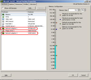
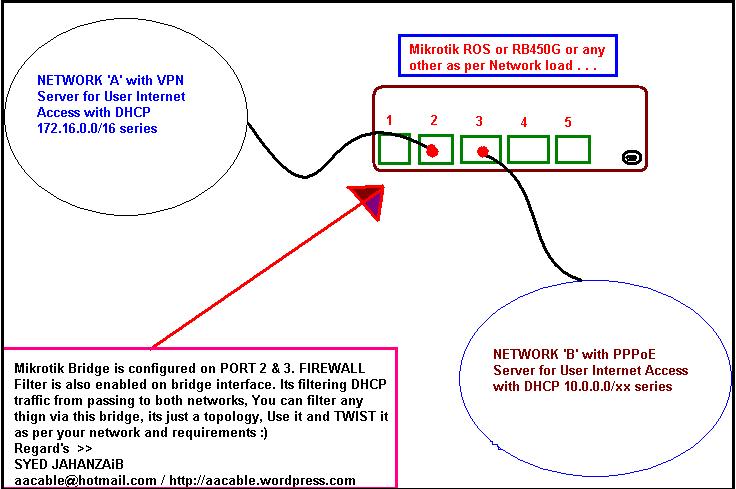
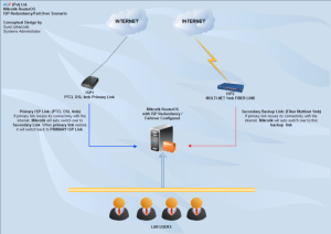
We have two WAN links and we want to use second WAN for fail over ONLY, No load balancing is required.
To achieve fail-over follow the below
Example:
LAN = 192.168.0.1
WAN1 GW= 192.168.1.1
WAN2 GW= 192.168.2.1
External Host ip that we want to monitor for the WAN status. (You can use your ISP’s DNS / Web server ip also or any one which is more reliable and preferably closer to you)
Google DNS = 8.8.8.8
TW DNS (PK) = 221.132.112.8
Following is complete script.
1# Make sure you change the interface names and IP addresses according to your network,
2# In DNS section, Use your ISP’s DNS ip addresses
3# You can use different host ip addresses for monitoring, preferably your primary ISP’s reliable servers like DNS or other. You can use other web sites ips too.
# apr/12/2013 10:41:20 by RouterOS 5.20
# Syed Jahanzaib / aacable@hotmail.com
# Web= http://aacable.wordpress.com
/ip address
add address=192.168.0.1/24 disabled=no interface=LAN network=192.168.0.0
add address=192.168.1.2/24 disabled=no interface=WAN1 network=192.168.1.0
add address=192.168.2.2/24 disabled=no interface=WAN2 network=192.168.2.0

/ip dns
set allow-remote-requests=yes cache-max-ttl=1w cache-size=5000KiB \
max-udp-packet-size=512 servers=208.67.222.222,202.141.224.34
# Or use your ISP's DNS

/ip firewall nat
add action=masquerade chain=srcnat disabled=no out-interface=WAN1
add action=masquerade chain=srcnat disabled=no out-interface=WAN2

#### Following is ROUTE section where we will be using check-gateway function to monitor external hosts from each wan

/ip route
add dst-address=8.8.8.8 gateway=192.168.1.1 scope=10
add dst-address=221.132.112.8 gateway=192.168.2.1 scope=10

add distance=1 gateway=8.8.8.8 check-gateway=ping
add distance=2 gateway=221.132.112.8 check-gateway=ping
The above fail over method works fine,when the WAN1 link will fail , it will automatically fail over to secondary link, and when the wan1 link becomes available all load will shift back to wan1 link. The only negative is that we are using single wan host to monitor, if that particular host (e.g 8.8.8.8) ping goes down and the rest is fine , wan1 link will still shift to secondary link. To avoid it use multiple hosts to monitor wan connectivity.
SCENARIO #2
FAIL OVER for Dual WAN links without Load Balancing using SCRIPT
![mikrotik-isp-redundancy]()
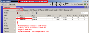
If you have 2 WAN Links , and you want to use Primary Link for Main internet usage, and in case Primary Link [WAN1] Looses its connectivity with the INTERNET (For example problem with the link between your modem and ISP or Problem between ISP link and the internet), then Secondary Link take its place, and when Primary link [WAN1] restores, it will become active again. You can use the following scripts.
You have to create two scripts for this purpose.
SCRIPT-1 will check Internet connectivity by ping to Google DNS 8.8.8.8 (You can change this value) using Default Primary Link[WAN1], if it fails to receive reply, it will change this route distance value to 3.
SCRIPT-2 will check internet connectivity using Primary Link, if it able to get reply from Google DNS IP 8.8.8.8, it will Primary Link Routedistance value to 1 again, thus primary link will become Active again.
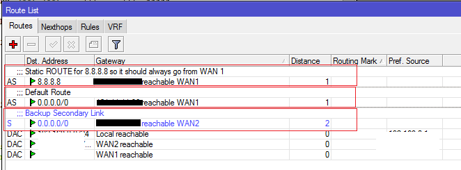
Route Distance values should be
[WAN1] PRIMARY link with Route DISTANCE value 1
&
[WAN2] SECONDARY link with Route DISTANCE value 2,
Make sure that you must do the following
1- Add following comment in the Default Primary Link [WAN1] route
Default Route
(If you don’t add this comment , Script wont be able to locate your default route)
2- Add static route for 8.8.8.8 [google dns] to make sure that monitoring to google dns always goes via primary link)
Ok It’s time to add Scripts
.
.
SCRIPT 1: (For WAN1 Down status checking)
It will check Internet Connectivity (with google DNS 8.8.8.8 , you can change it) Using Default Route (Primary Link[WAN1]), if it fails to get replies from it, it will change the distance value of primary link to 3 , so Secondary Link [WAN2] will automatically be promoted and it will act as the Primary Link for the connectivity.
Note: Following scripts have been taken from following link. I only modify it for my local need.
http://wiki.mikrotik.com/wiki/Improved_Netwatch_II
:local i 0; {:do {:set i ($i + 1)} while (($i < 5) && ([/ping 8.8.8.8 interval=3 count=1]=0))};
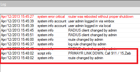
:if ($i=5 && [/ip route get [find comment="Default Route"] distance]=1) do={:log info "PRIMAYR LINK DOWN, Call 911 / 15,Zaib";
/ip route set [find comment="Default Route"] distance=3}
.
.
SCRIPT 2: (For WAN1 UP status checking)
It will again check Internet Connectivity (with Google DNS 8.8.8.8 ) using Default Route (Primary Link[WAN1]) as we have also set fixed route for 8.8.8.8 to always go throught primary link , If it get ping replies from teh google dns using the Primary Link [WAN1], it will change the Primary Link [WAN1] Route Distance back to 1 , so it will become Primary Link again.
:local i 0; {:do {:set i ($i + 1)} while (($i < 5) && ([/ping 8.8.8.8 interval=3 count=1]=1))};
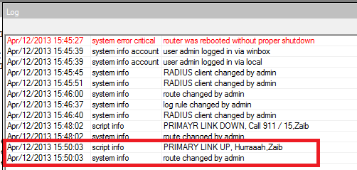
:if ($i=5 && [/ip route get [find comment="Default Route"] distance]=3) do={:log info "PRIMARY LINK UP, Hurraaah,Zaib";
/ip route set [find comment="Default Route"] distance=1}
Make sure that you Add following comment in the Default Primary Link [WAN1] route
Default Route
(If you don’t add this comment , Script wont be able to locate your default route)
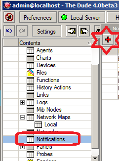
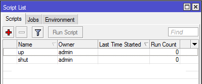
![default-route]() Now You can now schedule them to run SCRIPTs every 1 minute or whatever is ok for you.
Now You can now schedule them to run SCRIPTs every 1 minute or whatever is ok for you.
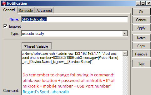
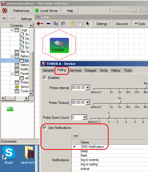
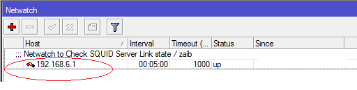
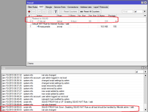
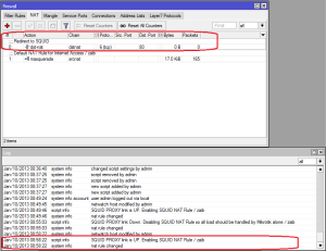
You will see following entries in LOG when WAN link goes DOWN and UP. You can also configure actions to email or SMS you if any link goes down for tack purposes, or if you want to be informed about the WAN status.
As showed in the image below . .
![1- down]()
![2- UP]()
.
.
.
.
SCENARIO #3
DUAL WAN LOAD BALANCING USING PCC WITH FAIL OVER without scripting (Very useful ![:)]() )
)
The following script does the two wan load balancing using PCC method, also if any of WAN link will fail , it will automatically fail over to secondary link, and when the particular failed link becomes available load will be start distributing among both links (remember it will not shift back previously made connections like downloads via idm etc. new packets will be distributed) .The only negative is that we are using single wan host to monitor, if that particular host (e.g 8.8.8.8) ping goes down and the rest is fine , wan1 link will still shift to secondary link. To avoid it use multiple hosts to monitor wan connectivity.
1# Make sure you change the interface names and IP addresses according to your network,
2# In DNS section, Use your ISP’s DNS ip addresses
3# You can use different host ip addresses for monitoring, preferably your primary ISP’s reliable servers like DNS or other. You can use other web sites ips too.
# apr/12/2013 11:13:43 by RouterOS 5.20
# Syed Jahanzaib / aacable@hotmail.com
# Web= http://aacable.wordpress.com
/ip address
add address=192.168.0.1/8 disabled=no interface=WAN1 network=192.168.0.0
add address=192.168.1.2/24 disabled=no interface=WAN2 network=192.168.1.0
add address=192.168.2.2/24 disabled=no interface=LAN network=192.168.2.0
/ip dns
set allow-remote-requests=yes cache-max-ttl=1w cache-size=5000KiB max-udp-packet-size=512 servers=208.67.222.222,202.141.224.34
# Use your OWN isp DNS ips , in this example I have used OPENDNS and other isp dns. Filtering is ON at opendns
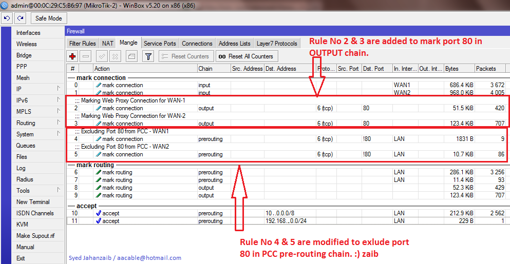
/ip firewall mangle
add action=accept chain=prerouting disabled=no dst-address=192.168.1.0/24 in-interface=LAN
add action=accept chain=prerouting disabled=no dst-address=192.168.2.0/24 in-interface=LAN
add action=mark-connection chain=input disabled=no in-interface=WAN1 new-connection-mark=WAN1_mark passthrough=yes
add action=mark-connection chain=input disabled=no in-interface=WAN2 new-connection-mark=WAN2_mark passthrough=yes
add action=mark-routing chain=output connection-mark=WAN1_mark disabled=no new-routing-mark=to_ISP1 passthrough=yes
add action=mark-routing chain=output connection-mark=WAN2_mark disabled=no new-routing-mark=to_ISP2 passthrough=yes
add action=mark-connection chain=prerouting disabled=no dst-address-type=!LAN in-interface=LAN new-connection-mark=WAN1_mark passthrough=yes per-connection-classifier=both-addresses-and-ports:2/0
add action=mark-connection chain=prerouting disabled=no dst-address-type=!LAN in-interface=LAN new-connection-mark=WAN2_mark passthrough=yes per-connection-classifier=both-addresses-and-ports:2/1
add action=mark-routing chain=prerouting connection-mark=WAN1_mark disabled=no in-interface=LAN new-routing-mark=to_ISP1 passthrough=yes
add action=mark-routing chain=prerouting connection-mark=WAN2_mark disabled=no in-interface=LAN new-routing-mark=to_ISP2 passthrough=yes
# Default masquerade rule for both WAN links
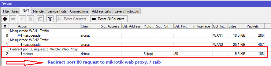
/ip firewall nat
add action=masquerade chain=srcnat disabled=no out-interface=WAN1
add action=masquerade chain=srcnat disabled=no out-interface=WAN2
### ROUTE SECTION ###
### Magic begins here
/ip route
add dst-address=8.8.8.8 gateway=192.168.1.1 scope=10
add dst-address=221.132.112.8 gateway=192.168.2.1 scope=10
## Now we create rules for Isp's routing mark:
add distance=1 gateway=8.8.8.8 routing-mark=to_ISP1 check-gateway=ping
add distance=2 gateway=221.132.112.8 routing-mark=to_ISP2 check-gateway=ping
## Create destinations to "virtual" hops to be use in further routes
add dst-address=10.0.0.1 gateway=8.8.8.8 scope=10 target-scope=10 check-gateway=ping
add dst-address=10.0.0.2 gateway=221.132.112.8 scope=10 target-scope=10 check-gateway=ping
## Add default routes for both isp's marked packets by mangle section
add distance=1 gateway=10.0.0.1 routing-mark=to_ISP1
add distance=2 gateway=10.0.0.2 routing-mark=to_ISP2
## Add default routes for no routing marks , For router itself
add distance=1 gateway=10.0.0.1
add distance=2 gateway=10.0.0.2
For more information, please visit
http://wiki.mikrotik.com/index.php?title=Advanced_Routing_Failover_without_Scripting
Regard’s
Syed Jahanzaib
Filed under:
Mikrotik Related ![]()
![]()


![RouterOS by Example - Stephen Discher[jz]]](http://aacable.files.wordpress.com/2013/09/routeros-by-example-stephen-discherjz.png?w=307&h=442)